Modulator Devices
Common Controls
 Enabled: Whether the modulator is running
 Map: Map the output of this modulator
 Trigger Map: Map the trigger output of this modulator
 Loop: Run the modulator in a continuous loop
 Trigger: Re-trigger the modulator from its start point
 MIDI: Configure MIDI input
AHDSR
Generates a multi-stage envelope based upon trigger or MIDI input
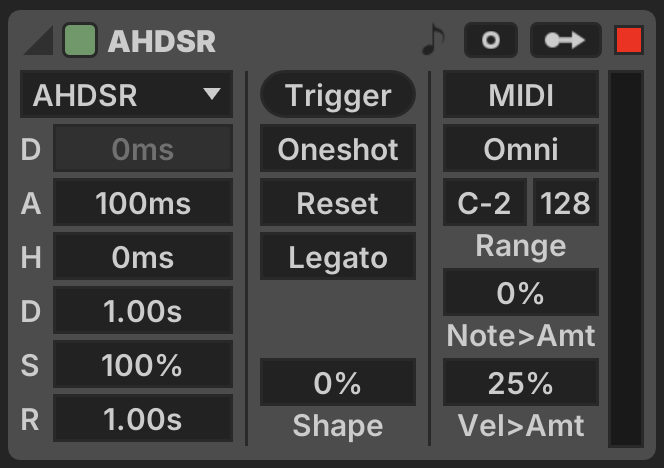
- Stage Mode: Which stages of the envelope are active
- Delay: A delay between trigger input and envelope attack
- Attack: Time for the envelope to reach peak value
- Hold: Time the envelope remains at peak input
- Decay: Time for the envelope to decrease from peak to sustain level
- Sustain: Level at which the envelope sustains
- Release: Time for the envelope to return to zero when disengaged
- Trigger: Mappable input trigger to engage the envelope
- Oneshot: When true, the envelope releases automatically
- Reset: When true, the envelope completely resets to zero on each new engagement
- Legato: When true, the envelope doesn't re-trigger when MIDI notes are held
- Shape: Applies exponential shaping to the Attack, Decay and Release phases
- MIDI: Whether MIDI triggering is enabled
- Note > Amount: Depth of modulation from MIDI note to envelope peak
- Velocity > Amount: Depth of modulation from MIDI velocity to envelope peak
See Envelope (music) on Wikipedia →
Band Filter
Averages a range of frequency bands from audio input
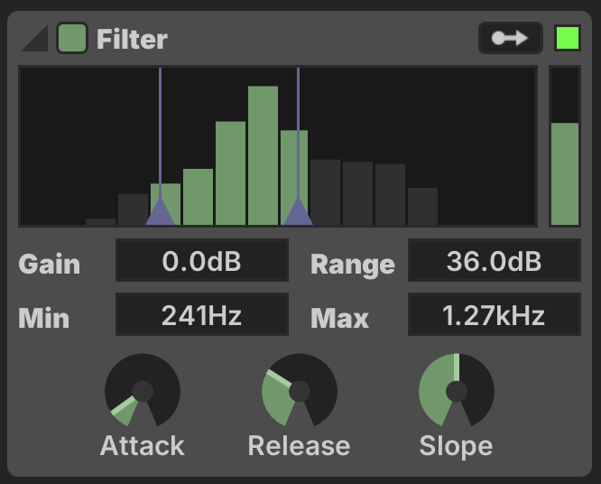
- Gain: Fixed gain applied to input signal
- Range: Meter range
- Min: Minimum frequency band
- Max: Maximum frequency band
- Attack: Meter attack time
- Release: Meter release time
- Slope: Meter response slope in dB / octave
Beat Detect
Detects beat transients in a given frequency range
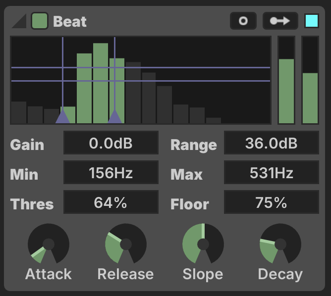
- Gain: Meter gain in decibels
- Range: Meter range in decibels
- Min Freq: Minimum frequency to detect
- Max Freq: Maximum frequency to detect
- Threshold: Meter level required to trigger the detector
- Floor: Level the meter must fall to before re-firing, percentage of Threshold
- Attack: Meter response time when the signal increases
- Release: Meter response time when the signal decreases
- Slope: Slope of the meter response across frequencies, in decibels/octave
- Decay: Duration of the generated ramp output when a beat is detected
The Min Freq, Max Freq, Threshold and Floor settings are represented visually and can be dragged using the mouse.
Outputs
The Beat Detect generates three distinct modulation outputs.
- Trigger: outputs when the detector is triggered
- Average: The first vertical meter shows the average level of the detector's frequency range
- Beat: When a beat is detected, the second vertical meter generates a downwards linear ramp with timing set by the Decay parameter
Use the Trigger output in combination with other modulators to generate a more complex response.
Comparator
Generate a boolean output by comparing input values
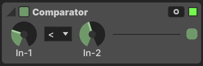
- In-1: First input value
- In-1: Second input value
- Comparison: What type of comparison to perform
The Trigger mapping output fires whenever the comparison output changes.
Cycle
Generate a cyclical linear ramp
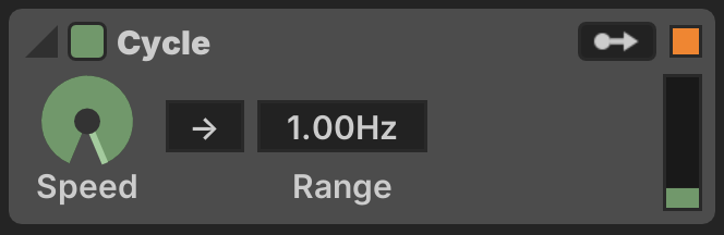
- Speed: Cycle speed
- Polarity: Whether speed knob is positive-only or bidirectional
- Range: Range of speed knob
Damper
Interpolate between an on and off value
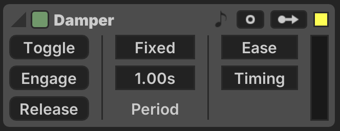
- Toggle: Toggles the damper on/off state
- Engage: Sets the damper to on state
- Release: Sets the damper to off state
- Timing: Time damper takes to change state
- Fixed: Absolute time unit
- Sync: Tempo time division
- Ease: Apply ease-out smoothing to the damper motion
- Timing: Set fixed times at which the damper operates
DMX Channel
Creates a modulation source from DMX input
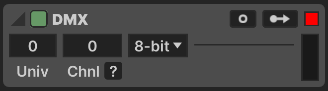
- Universe: DMX universe number (
0-indexed) - Channel: DMX channel offset (
0-511) - Mode: DMX Mode
- 8-bit: A single DMX channel value
- 16-bit: Two adjacent DMX channel values form a 16-bit value (MSB first)
- Range: A range of
[Min-Max]on a single DMX channel is used
DMX Color
Sets global Color Palette colors from DMX input
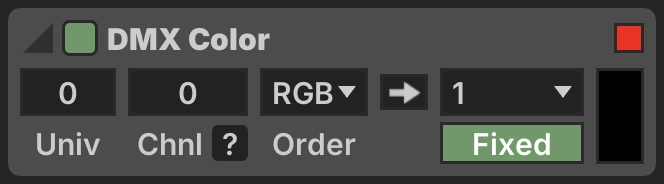
- Universe: DMX universe number (
0-indexed) - Channel: DMX channel offset (
0-511) - Order: DMX color byte order
- Palette : Update Color Palette with DMX color
- Index: Which Color Palette swatch position to update
- : Whether to force the Color Palette mode to
Fixedwhen updating
Envelope
Generates a manually-edited multi-step envelope
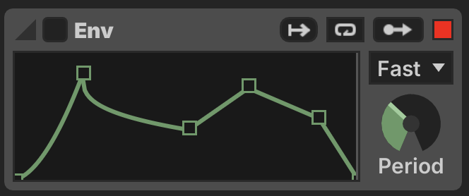
Editing
- Double-click to add points to the envelope
- Click and drag to move an envelope point
- Hold ⌘ then click and drag up/down to shape interpolation curves
Timing
- Fast: Envelope period set up to 1 minute
- Slow: Envelope period set up to 15 minutes
- Sync: Envelope set to a tempo division
Interval
Generates a trigger output when an interval elapses
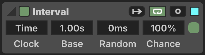
- Timer: Triggers based upon elapsed time
- Base: Base interval time
- Random: Range of random timing variation applied to each interval
- Sync: Syncs triggers to tempo division
- Lock: Lock tempo divisions to master metronome
- Division: Tempo division specified for intervals
- Chance: Probability of the output firing when the interval elapses
Knobs
Generic mappable macro knobs
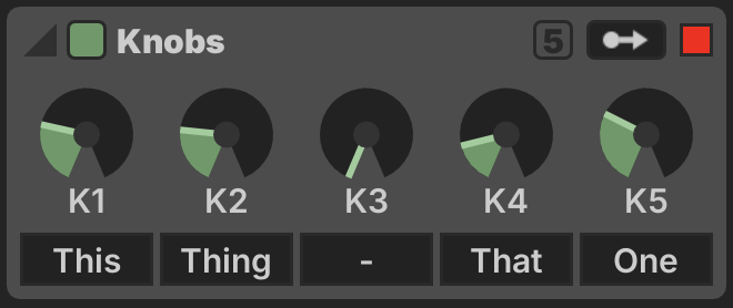
Offers a set of generic knobs that can be used as modulation sources, typically used to create macro controls whereby a single knob can control many parameters in a project. This is also commonly used as a relay point for OSC input.
Use the button in the header to toggle between 5 or 8 knobs. Knobs may be given arbitrary text labels, these labels serve no function and are purely to reminder the user of the intended purpose.
LFO
Generates an adjustable LFO waveshape
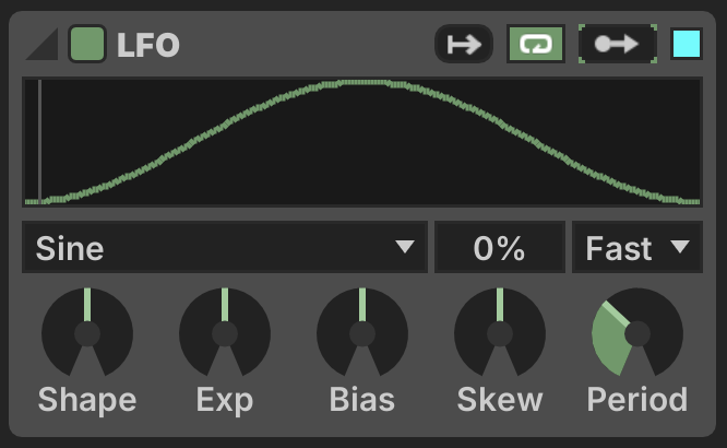
Waveshape
- Wave: Base waveshape used by the low frequency oscillator
- Phase: Applies a fixed phase offset to the wave
- Shape: Biases the wave towards the average or extreme values
- Exp: Applies exponential shaping to the wave's time-basis
- Bias: Applies shaping of the time-basis towards the average or extremes
- Skew: Skews the time-basis towards the start or end of cycle
Timing
- Fast: Envelope period set up to 1 minute
- Slow: Envelope period set up to 15 minutes
- Sync: Envelope set to a tempo division
Logic
Computes the output of boolean logic between multiple inputs
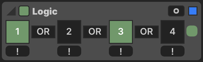
- In-N: Input value for position N
- Not-N: Inverts the value for position N
- Op-N: Logical operation to combine positions N and N+1
The computation is performed from left-to-right.
(((in₁ ×¹ in₂) ײ in₃) ׳ in₄
MIDI Note
Converts incoming MIDI notes into trigger modulation

- Mode: Whether to retrigger when Legato notes are played
The last-played pitch (P) and velocity (V) are represented as horizontal meters which can also be used as modulation sources.
Multi Trig
Converts a single trigger input into multiple outputs
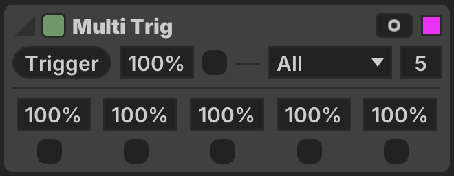
- Trig: Input trigger
- Chance: Chance that the input trigger activates the outputs
- Mode: How the input trigger is mapped to output triggers
- All: All outputs are activated
- Random: A random output is chosen
- Cycle: Outputs are cycled through
[1, 2, 3, 4, 5, 1, 2, 3, ...] - Reverse: Outputs are cycled through
[5, 4, 3, 2, 1, 5, 4, 3, ...] - Flip: Outputs are cycled
[1, 2, 3, 4, 5, 4, 3, 2, 1, 2, 3, ...]
- Num Outs: How many output triggers are active
- Chance N: Probability that each output fires when activated
Noise
Generates pseudorandom movement using a noise algorithm

- Speed: Rate of change in the noise output
- Range: Scale of the speed knob
- Level: Midpoint level of the noise generator
- Contrast: Contrast depth of the noise generator
- Min: Minimum output level
- Max: Maximum output level
Algorithm
- Perlin: Perlin noise
- Ridge: Ridged fractal noise
- FBM: Fractal Brownian Motion
- Turbulent: Perlin noise with turbulence
- Static: Totally random unperiodic signal, only Level and Contrast apply
The noise algorithms offer various controls to control their behavior.
Operator
Compute a mathematical operation on two inputs
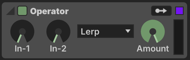
- In-1: First input value
- In-2: Second input value
- Operation: Operation to perform on input values
- Amount: Blends from In-1 to the result of the computation
Quantizer
Defers an input trigger until a tempo division elapses

- Trigger: Queue an input trigger
- Quantization: Which tempo division to wait for to fire the output
See also Launch Quantization →
Randomizer
Randomizes a value based on timing or trigger input
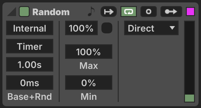
- Chance: Chance that a new value is set when the interval fires
- Min: Minimum output value
- Max: Maximum output value
- Lerp Mode: How the modulator output changes
- Direct: Immediate jump to new random value
- Damped: Damping based upon Speed (units / second) and Acceleration (time to reach max speed)
- Smooth: Exponential smoothing with a Time and Window parameter
Internal Triggering
- Timer: Triggers based upon elapsed time
- Interval: Base interval time
- Random: Range of random timing variation applied to each interval
- Sync: Syncs triggers to tempo division
- Lock: Lock tempo divisions to master metronome
- Division: Tempo division specified for intervals
External Triggering
- Trigger: Manually trigger a new random value
The Trigger output fires when the randomizer interval activates.
Scaler
Scales input by a linear factor with shaping
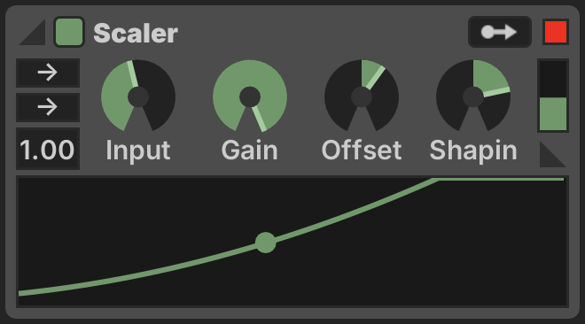
- Input Polarity: Whether input is positive-only or bidirectional
- Gain Polarity: Whether gain is positive-only or bidirectional
- Factor: Range of the gain knob
- Input: Input value
- Gain: Gain percentage, to be multiplied by Factor
- Offset: Fixed offset added to the result
- Shaping: Exponential curve applied to the output
Smoother
Smoothes input with exponential decay
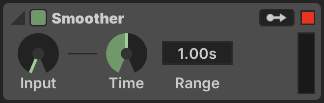
- Input: Input value
- Time: Smoothing time
- Range: Range of the Time knob
Sound Object
Tracks a spatial audio source in 3D space

Position
Sound Object positioning is relative to the Sound Stage defined on the MODEL tab.
- Azimuth: Azimuth about the ground plane (clockwise rotation)
- Elevation: Elevation above or below the ground plane
- Distance: Distance from the center
- ADM Sync: When active, the position syncs automatically to messages received via ADM-OSC for the given Object ID (requires OSC input to be active)
Sound Object positions are used to generate visual content by the Sound Object pattern and Sound Object effect.
Metering
- Ceiling: Maximum meter input
- Floor: Minimum meter input
- Attack: Meter attack time
- Release: Meter release time
- Meter Source: Determines where this Sound Object draws metering information from
The two vertical bars indicate the raw meter input and the smoothed output with range limiting.
Spring
Applies a spring model to input
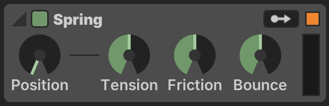
- Position: Input spring position
- Tension: Stiffness of the spring (strength of response)
- Friction: Friction of the spring (amount of oscillation)
- Bounce: How much the spring "bounces" off extreme values
Step Sequencer
Generates trigger outputs based upon a sequenced pattern
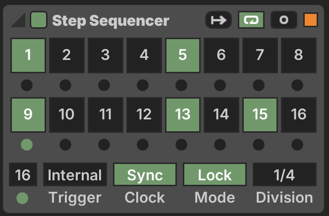
- Step-N: Whether the trigger is active on this step
- Num Steps: How many steps the sequencer loops through
- Trigger: Iterate steps based upon Internal clock or External trigger input
Hold the ⌘ key and click the output indicator in the bottom right corner to manually fire the trigger output.
Stepper
Iterates through a sequence of values
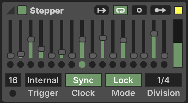
- Step-N: Sets the value for each step
- Num Steps: How many steps are active in the sequence loop
- Trigger: Iterate steps based upon Internal clock or External trigger input
The Trigger output fires on any step event (e.g. to trigger an envelope on each step).
Switches
Generic mappable macro switches
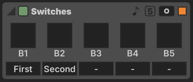
Offers a set of generic toggles that can be used as mapping sources, typically used to create macro controls whereby a single toggle can control many parameters in a project. This is also commonly used as a relay point for OSC input.
Use the button in the header to toggle between 5 or 8 switches. Switches may be given arbitrary text labels, these labels serve no function and are purely to reminder the user of the intended purpose.
MIDI ![]() settings can be configured so that a range of MIDI notes toggle the switches.
settings can be configured so that a range of MIDI notes toggle the switches.
Timer
Generates trigger output at a fixed time
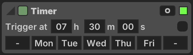
- Hours: Hour of day
- Minutes: Minute of hour
- Seconds: Second of the minute
- Day of Week: Whether the timer is active on this day of the week
Hold the ⌘ key and click the output indicator to manually fire the trigger output.
Triggers
Generic mappable macro triggers

Offers a set of generic triggers that can be used as mapping sources, typically used to create macro controls whereby a single trigger can control many parameters in a project. This is also commonly used as a relay point for OSC input.
Use the button in the header to toggle between 5 or 8 triggers. Triggers may be given arbitrary text labels, these labels serve no function and are purely to reminder the user of the intended purpose.
MIDI ![]() settings can be configured so that a range of MIDI notes activate the triggers.
settings can be configured so that a range of MIDI notes activate the triggers.