Audio
Real-time Audio can be used as a modulation source in Chromatik to create dynamic, musically responsive effects. Audio settings are configured in the AUDIO section of the left-pane GLOBAL tab.
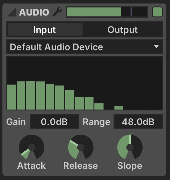
The top bar includes a Decibel Meter, which can be used as a modulation source, as well as an Enabled ![]() button to toggle whether the audio engine is active.
button to toggle whether the audio engine is active.
I/O
Audio Input/Output is selected via a toggle set. When Input is active, a drop-down menu displays the available input audio devices. When Output is active, a strip of controls allows selection of a WAV/AIFF audio file, with controls for Play/Pause, Trigger, Loop and Load.
These modes are exclusive, they cannot be used simultaneously. The Output mode is only recommended for basic testing. If you want more advanced multi-channel audio functionality or timeline-based editing, Chromatik is designed to work well side-by-side with DAW applications.
Graphic Meter
The Graphic Meter shows 16 frequency bands of audio response, each of which is can be used as a modulation source.
The response of the meter is adjustable, with settings that also affect the Decibel Meter above.
- Gain: Decibel adjustment to the source signal
- Range: Total range of the meter in decibels
- Attack: Meter response time when amplitude increases
- Release: Meter response time when amplitude decreases
- Slope: Slope of the meter response across frequencies, in decibels/octave
External Metering
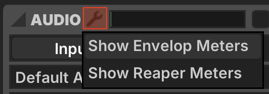
Metering from external applications is available via the Preferences ![]() button.
button.
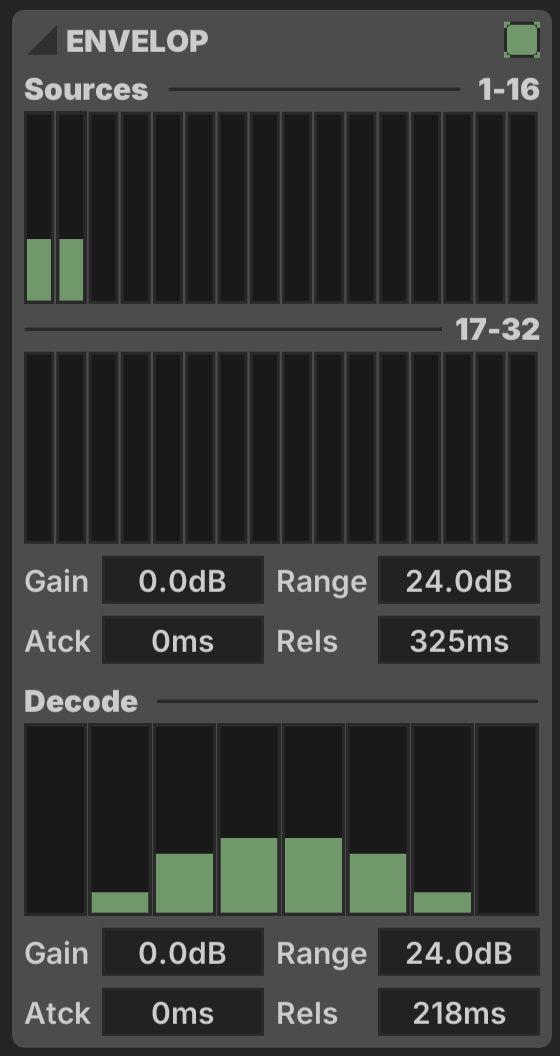
Envelop for Live
Envelop for Live delivers up to 32 individually metered sound sources and an 8-channel Ambisonic decode when OSC input from E4L is configured.
Reaper
Up to 32 individual channel meters plus a Master level meter can be received from Reaper.
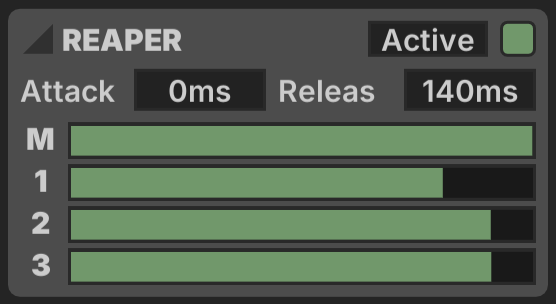
This requires configuring Chromatik as an OSC Control Surface in Reaper Preferences.
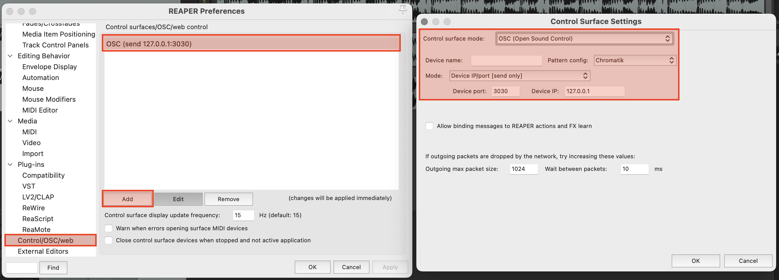
Download the Chromatik Control Surface OSC definition →
Beat Detection
Primitive transient detection is implemented in the Beat Detect modulator.
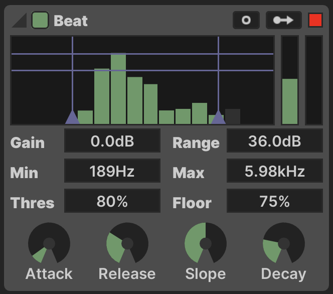
Controls
- Gain: Meter gain in decibels
- Range: Meter range in decibels
- Min Freq: Minimum frequency to detect
- Max Freq: Maximum frequency to detect
- Threshold: Meter level required to trigger the detector
- Floor: Level the meter must fall to before re-firing, percentage of Threshold
- Attack: Meter response time when the signal increases
- Release: Meter response time when the signal decreases
- Slope: Slope of the meter response across frequencies, in decibels/octave
- Decay: Duration of the generated ramp output when a beat is detected
The Min Freq, Max Freq, Threshold and Floor settings are represented visually and can be dragged using the mouse.
Outputs
The Beat Detect generates three distinct modulation outputs.
- Trigger:
 outputs when the detector is triggered
 - Average: The first vertical meter shows the average level of the detector's frequency range
- Beat: When a beat is detected, the second vertical meter generates a downwards linear ramp with timing set by the Decay parameter
Use the Trigger output in combination with other Modulator devices to generate a more complex response.